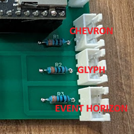
Need help or have questions?
Join our community of builders on Discord to share your progress, ask for troubleshooting, or just chat about the project!
💬 Join the OpenGate DiscordPrerequisites
- Own a 3D printer, or order the printed parts online.
- Have basic electronics knowledge. Only a few solder joints are required!
- Power Supply: The gate must operate on a 5V power supply. An external 5V supply connected to the screw terminal is strongly recommended.
- USB power is only suitable if the LED brightness is kept below 20%. Higher brightness may cause voltage drops.
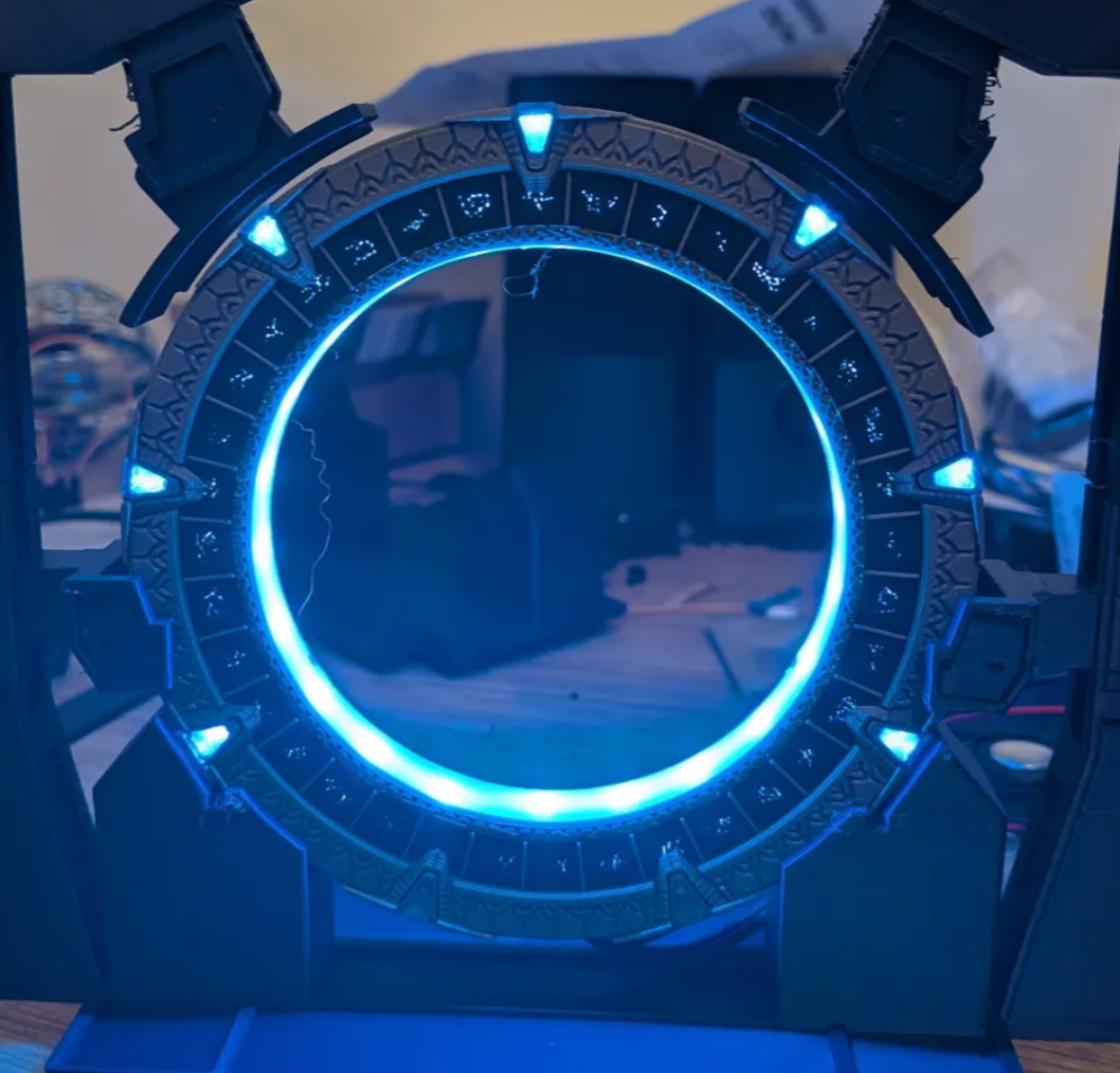
Required Hardware
LED Strips:
- 3 x WS2812B 5V LED strips (96 LEDs/m): 36 LEDs for the glyph ring, ~44 LEDs for the chevron ring, 36 LEDs for the event horizon (116 LEDs ≈ 1.2m minimum — buy a bit more for margin, see the BOM page). Trim any excess during assembly.
- Important: Make sure the factory solder joint is not located within the Glyph Ring strip, as it requires perfectly consistent LED spacing.
Electronics:
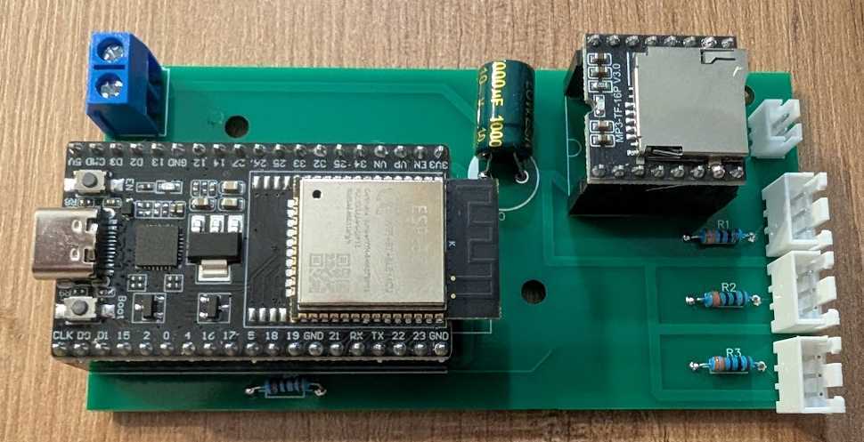
- 1 x 16V (or 25V) 1000 µF electrolytic capacitor & 3 x 330 Ω resistors.
- 1 x DFPlayer Mini + microSD card (FAT32).
- 1 x ESP32-WROOM-32D (38-pin version).
- 1 x 8 Ω/3 W speaker & JST-PH 2.0 connector.
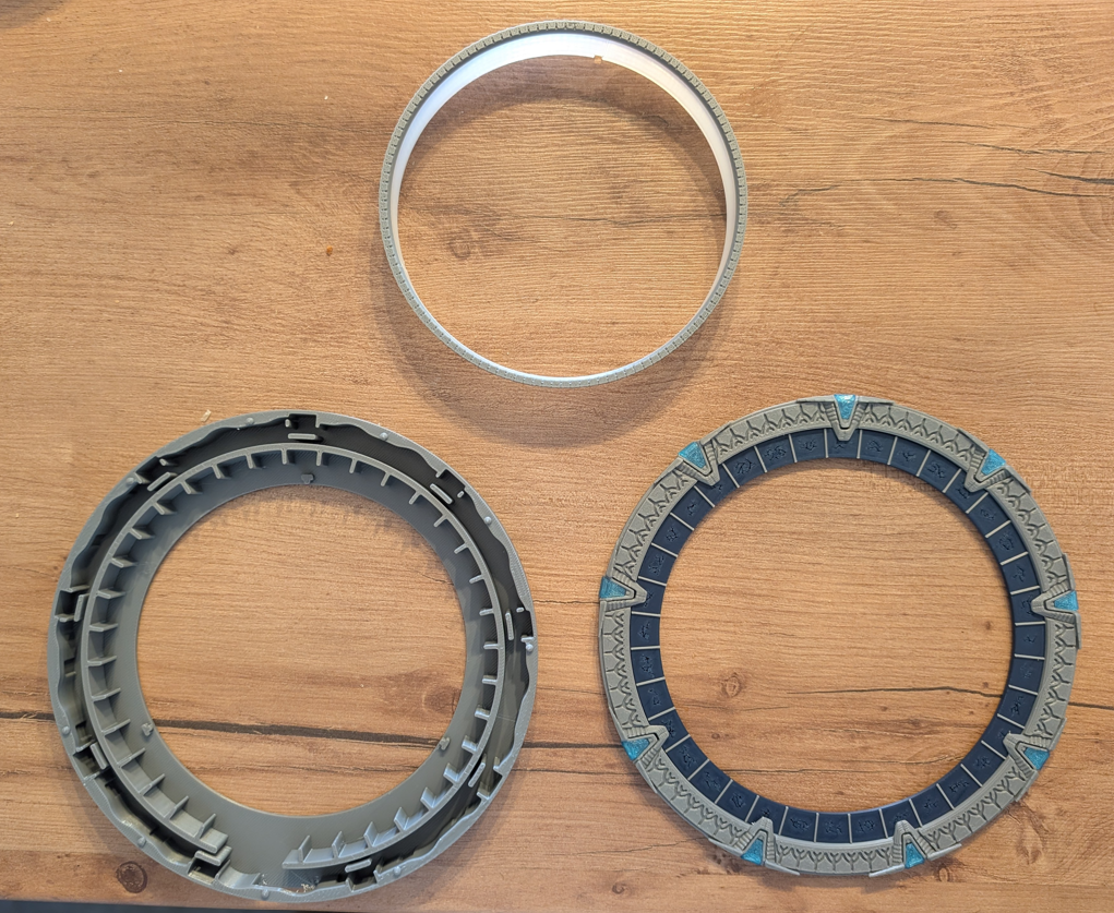
Printing the Parts
- Core Ring: Grey PLA, supports required.
- Internal Ring: Grey PLA + translucent PLA, no supports required.
- External Ring: Grey PLA, supports required.
- Glyph Ring: Dark blue PLA (0.2 mm nozzle recommended for detail).
- Chevrons: Translucent light blue PLA.
Circuit Preparation
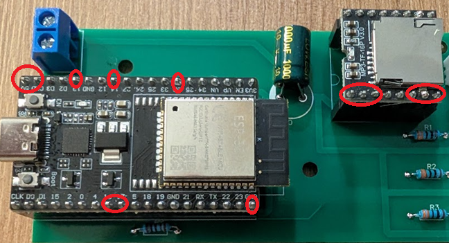
I strongly recommend using 2.54 mm female pin headers for the ESP32 and DFPlayer Mini to make replacements easier.
WARNING: Do not reverse the 5V (+) and GND (-) connections. Reversing the polarity will destroy your NeoPixel strips.
Time-Saving Tip: You do not need to solder all 38 ESP32 pins. Only solder the used pins: 5V, GND, GPIO13, GPIO14, GPIO32, GPIO16, GPIO17.
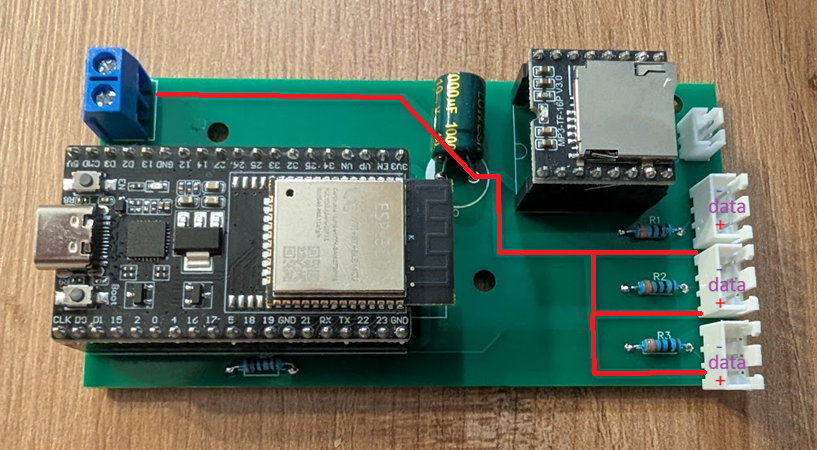
Gate Assembly
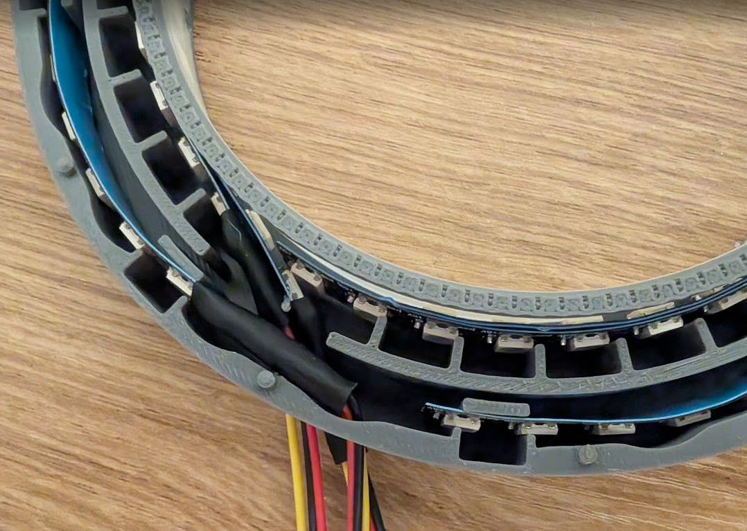
Simply place the LED strips inside the Core Ring. It is not a problem if your LEDs are not perfectly centered; the firmware includes an option to illuminate adjacent LEDs.
Use a low-temperature hot glue gun (100-120°C) to secure everything in place without damaging the strips.
Tip: Label each NeoPixel strip with a marker before installation to identify which strip connects to which PCB connector.
Firmware Installation
Connect your ESP32 to your computer using a USB cable and open the flash tool via Google Chrome at /flash/.
Select your gate model, connect, and hold the BOOT button to start. Once complete, it will start in Wi-Fi Hotspot mode.
Format your microSD card in FAT32 and put the mp3 folder at the root of the microSD card
Connect to the ESP32 network to configure your Wi-Fi and Stargate access key.
Joining the Network
To support more than 100 simultaneous connections and maintain control, the project runs on a dedicated server.
You can register your Stargate on a public directory to receive incoming wormholes (optional).
To join the official network, a voluntary donation of at least €1 is asked to cover server costs. You will then receive your personal credentials.
buymeacoffee.com/opengateproject