Need help or have questions?
Join our community of builders on Discord to share your progress, ask for troubleshooting, or just chat about the project!
💬 Join the OpenGate DiscordPCB (Gerber Files)
Download the Gerber files for the official SG-1 Motorized PCB and send them straight to any PCB fab (JLCPCB, PCBWay, etc.) to get your board manufactured — a how-to-order text file is included in the zip.
Not comfortable ordering or assembling a PCB yourself? Reach out on Discord — we can help you get one fully assembled.
3D Printed Parts
Download the 3D models for the motorized SG-1 gate:
Hardware & Sounds
Electronic parts that can't be assembled on the official PCB — if you want to order them:
- 1) NEMA17 stepper motor — recommended models: 17HS4023, 17HS4401, 17HS3401, or 17HS15-1504S. 1.3–1.5A is enough, and the motor's depth doesn't really matter (tried both 17HS4023 and 17HS15-1504S on my prototype). I used this one (17HS15-1504S) on my own gate.
⚠️ Two important things:- The cable has to be a JST-XH 6-pin to Dupont 4-pin cable, like this one.
- NEMA17 motors aren't all wired the same way — usually it's "ABAB" for the pins, but sometimes it's "AABB". The PCB has both options, so you can try either — just never plug both at the same time.
- 2) DRV8825 stepper driver — example.
- 3) DFPlayer Mini (+ any microSD card formatted FAT32) — example.
- 4) 3W 8Ω speaker — example.
- 5) LM2596 buck converter (adjustable) — example. Untested with the LM2596S variant (the one with a 7-segment display), but it should work just as well.
Hardware to plan for:
- M3 inserts (2 to 4mm) ×2
- M3 screws (10 to 12mm) ×4 — M3×10mm is the ideal length, but M3×12mm also works
- Two COB LED strips, 5mm, 5V, 100 LEDs/m (the exact LED count on the strip doesn't matter much for this gate)
Understanding the Parts
- The ramp: both the gate and the NEMA17 motor mount onto this piece, using M3 inserts (glued in, or melted into the plastic with a soldering iron) and M3 screws.
- The ring core: the gate's main body. This is where the glyph and chevron LED strips are routed, and where the rotating glyph ring sits.
- The rotating glyph ring: sits directly inside the ring core. It's held in place by the 9 tabs near the chevrons at the back, by the NEMA17, and by the front ring of the gate.
- The front ring: clips onto the ring core to close up the gate. Glue the 9 chevrons — printed in transparent red — onto it.
- The inner ring / event horizon: the last piece to go on. It can be secured with glue or with poster putty (Patafix).
Printing tips: use at least 80% infill for the motor gear and the rotating glyph ring. No supports are needed for any part except the rotating glyph ring.
Practical tips: sand the back of the rotating glyph ring to prevent friction during rotation. The gate is very easy to take apart — if something feels off, don't hesitate to backtrack a step.
Mount the Motor & Ring Core
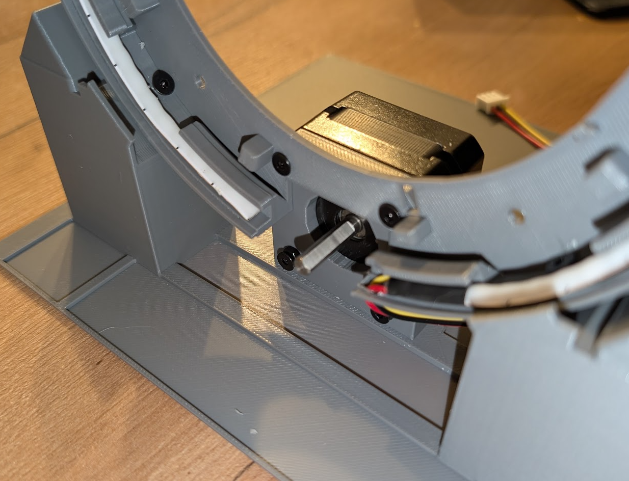
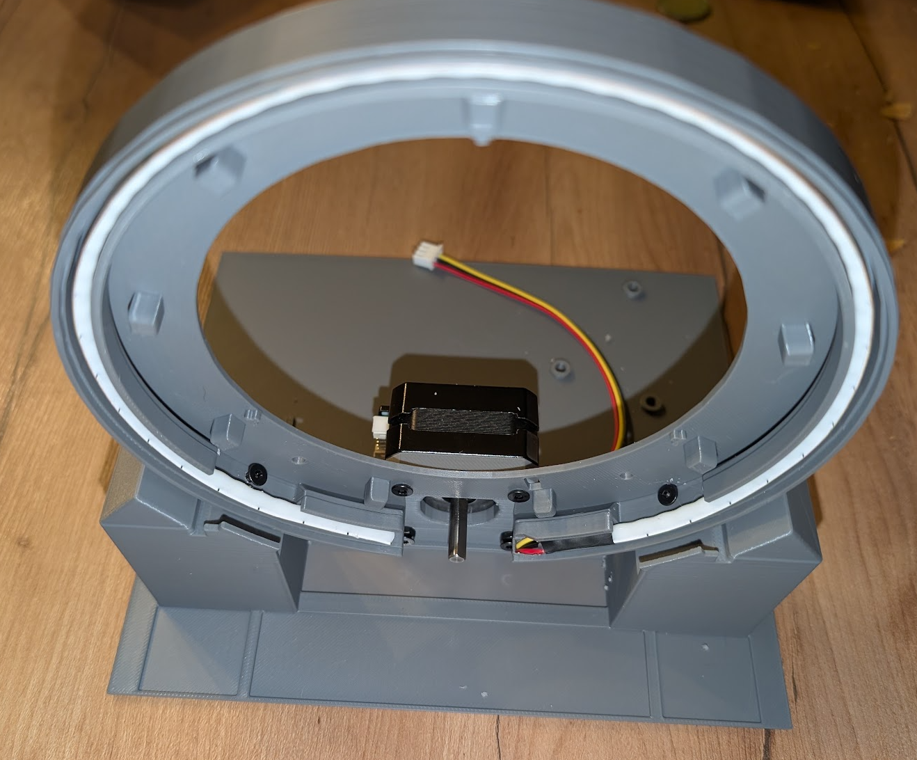
Place the NEMA17 onto the ramp and screw it in using the two lower screws.
Then screw the ring core onto the ramp using the two lateral M3 screws, plus the two lower central screws — these also secure the top of the NEMA17.
Note: a few extra, more lateral holes are already there for possible future ramp designs.
Chevron LED Strip
Once the gate is firmly mounted, run the 5mm 5V COB LED strip for the chevrons around the outside of the gate.
A small hole near the lower right of the motor lets the cable pass through.
Motor Gear & Spacer
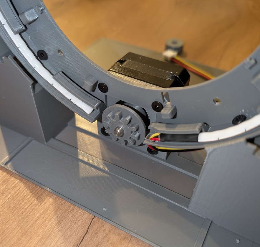
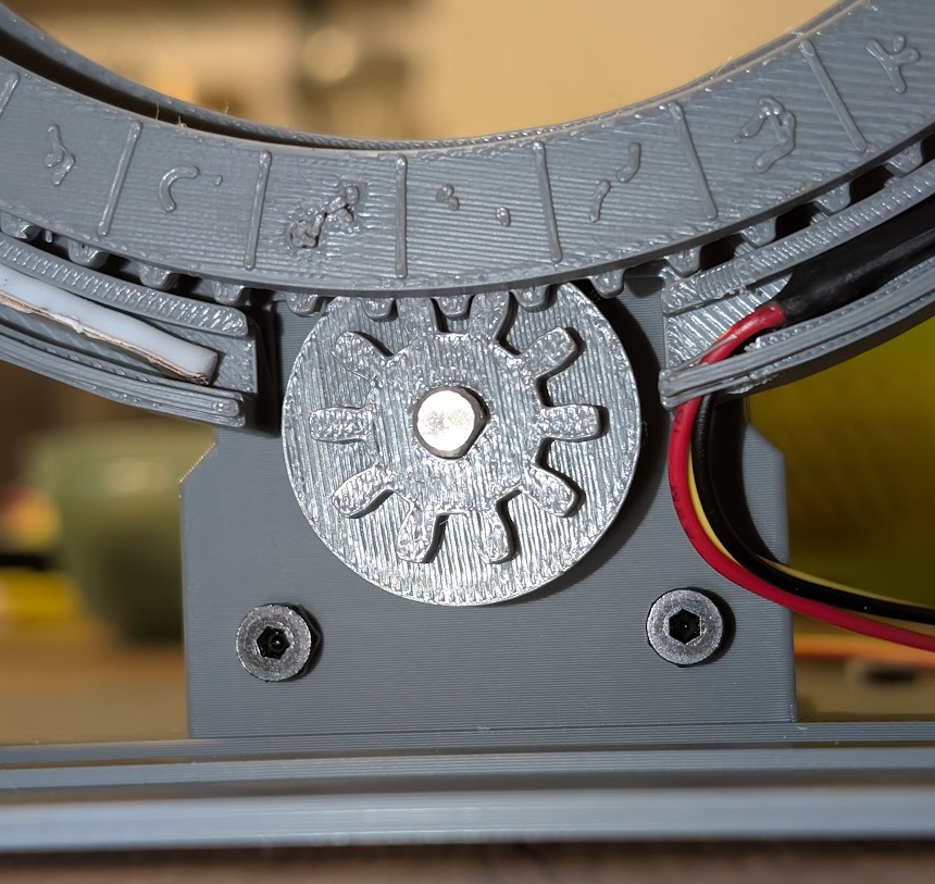
Place the NEMA17 gear and its spacer directly onto the motor shaft.
The spacer is optional, but it helps keep the gear from sliding back over time — it should be 10 to 12mm (adjust the size as needed). What matters most is that, once assembled, the rotating glyph ring and the gear stay well aligned and parallel.
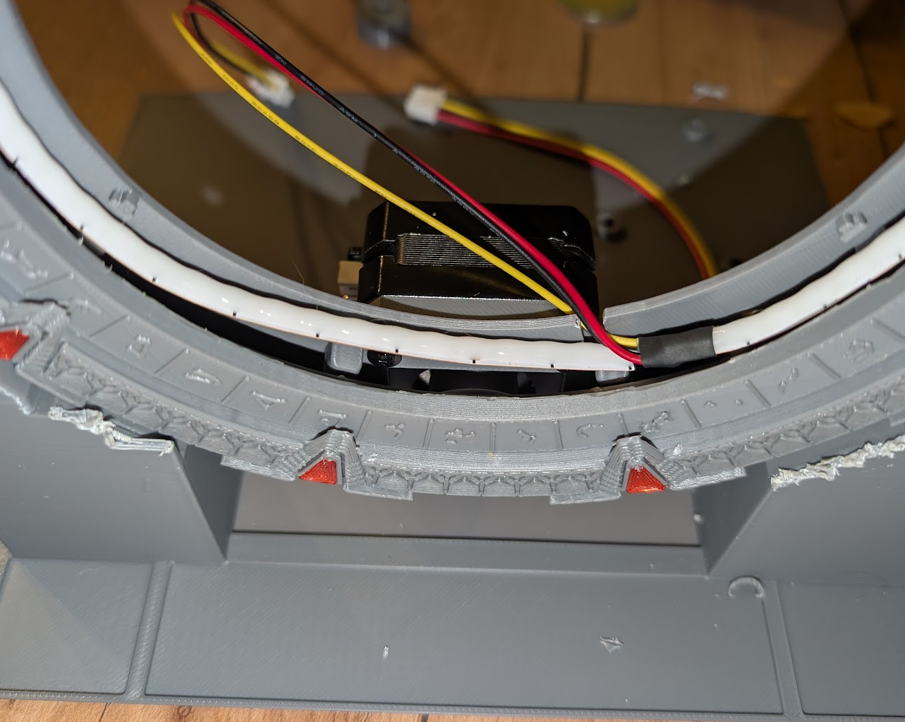
Event Horizon LED Strip
Run the event horizon LED strip between the notch that holds the inner ring and the tabs that hold the rotating glyph ring.
A few dots of glue are recommended to keep the strip from rubbing against the rotating ring.
Inner Ring
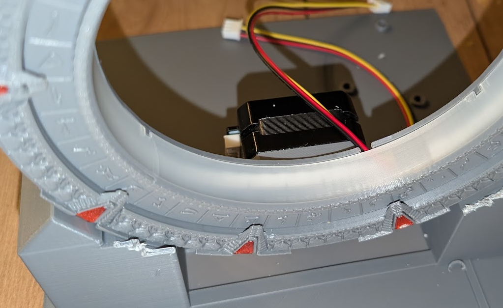
Place the inner ring — this is the final piece of the mechanical assembly.
Calibrate the Drivers (Before Installing Anything)
Both the DRV8825 stepper driver and the LM2596 buck converter need to be calibrated before they're plugged into the PCB — it's much easier to reach the trim potentiometer with a multimeter probe while the board is bare.
1) DRV8825 — current limit (Vref)
Follow this video for the actual calibration procedure (multimeter on the trim pot, small screwdriver adjustment).
For the target value: these driver boards almost all use the same 0.1Ω sense resistors, which gives the standard formula Vref = motor current ÷ 2. With the 1.3–1.5A motors recommended above, that puts you around 0.65V — a safe starting point with plenty of torque for a decorative gate, without pushing the driver into excess heat. If you notice missed or skipped glyphs after assembly, nudge it up toward ~0.75V; if the driver gets hot to the touch, back it down instead.
2) LM2596 buck converter — output voltage
Follow this video and set the output to exactly 5.0V. This is what powers the ESP32, DFPlayer, and LED strips — double-check it before plugging anything else in.
PCB Overview
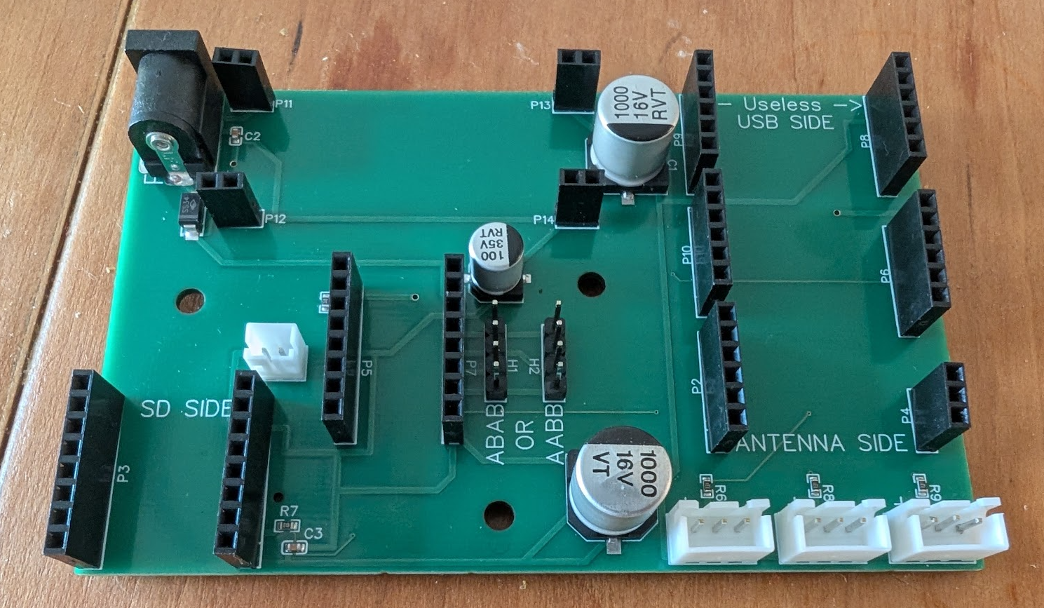
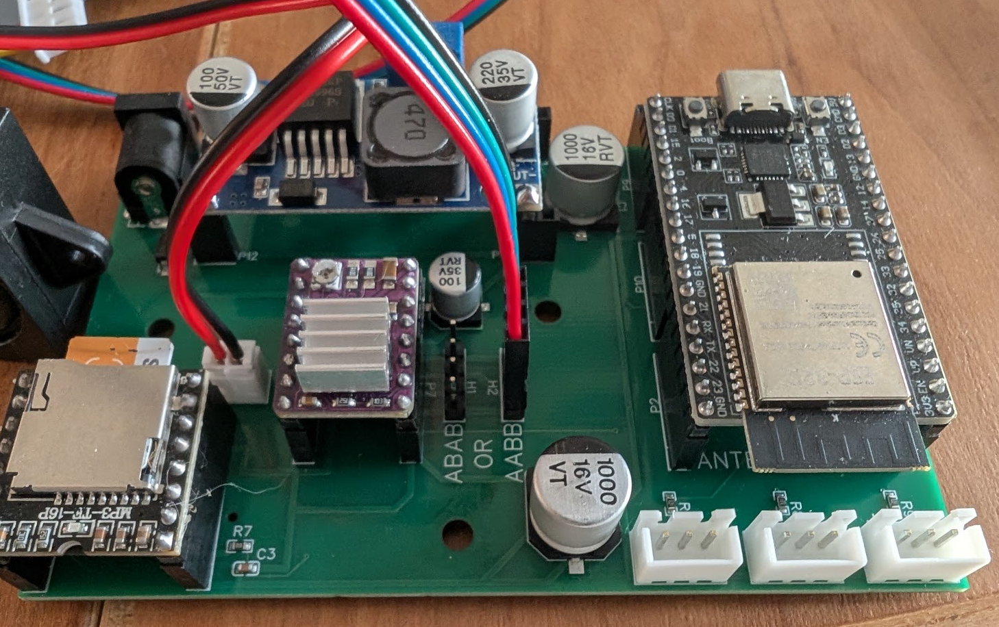
You can order this PCB blank from the Gerber files (step 1), or have it pre-assembled — the parts were deliberately chosen to generally be in stock at JLCPCB, so the same Gerber works fine for their assembly service.
- ESP32 female header: because parts were picked for stock availability, the header has more pins than the ESP32 actually needs. That's normal — clip it in the correct orientation, and don't populate the pins marked
<-- USELESS -->on the silkscreen. - NEMA17 connector — two 4-pin footprints: you'll see two groups of 4 pins, labeled "ABAB" and "AABB". Plug the motor into only one of them — never both at once. Which one depends on how your specific motor is internally wired (usually AABB, but check the motor you bought). Not sure? Try one, then the other if the ring doesn't turn — the correct footprint is simply the one that makes the motor spin.
- Ring lands on the wrong glyph after calibration: this means the motor's Dupont connector is plugged in mirrored. Either flip it 180°, or leave it as-is and tick "Reverse ring direction" in the Motor Calibration panel on the DHD — no rewiring needed either way.
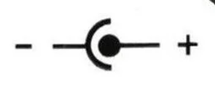
- Power input — 12V DC only: use a standard 12V DC barrel jack power supply. Do not use anything above 12V. The center pin must be positive — check the polarity symbol printed on your power adapter's cable against the one below. Getting this wrong will fry the entire board.
- DFPlayer microSD card: reuse the exact same mp3 pack you'd use on any other SG-1 gate — it's shared across variants, nothing motor-specific to add.
- Buck converter placement: it plugs in right next to the power input, in the correct orientation. You'll notice 4 pairs of 2-pin female headers instead of single-pin ones — that's simply because 1-pin headers aren't easy to source, the 2-pin ones are just used as pairs.
- LED strip polarity: on every LED strip connector, + / 5V is on the LEFT — there's a small "+" printed on the PCB silkscreen next to each one. Wiring a strip backward will fry it, and you'll need to replace that strip entirely.
Fully Assembled PCB
Flash the Firmware
Connect your ESP32 to your computer using a USB cable and open the flash tool via Google Chrome or Edge at /flash/.
Select SG-1 (Motorized), connect, and hold the BOOT button to start. Once complete, it will start in Wi-Fi Hotspot mode.
While you're at it: format your microSD card as FAT32, put the mp3 folder (downloaded in step 3) at its root, and insert it into the DFPlayer.
⚠️ Make sure the DRV8825 and buck converter are already calibrated (step 10, above) before powering the board on for the first time.
Compiling from source instead? Open stargate.txt in the Arduino IDE (save/rename it as a .ino), keeping sg1_motor.h and webpage_sg1.h in the same folder. Near the top of the file, under "PROFIL DE PORTE", uncomment the line #define GATE_SG1_MOTOR — make sure it's the only GATE_* line uncommented — then select your board and port and upload as usual.
Once flashed, the gate boots into its own Wi-Fi hotspot for setup — same as every other OpenGate model, covered next.
Joining the Network
Connect to the Stargate-Setup-XXXX Wi-Fi network your gate creates (open, no password needed). A setup page should open automatically — if it doesn't, just open a browser and it'll redirect you there.
Enter your home Wi-Fi details, plus your MQTT credentials if you've already joined the official network. Save & reboot: the gate connects to your Wi-Fi, and the confirmation page tells you exactly where to find it — http://Stargate-<name>-XXXX.local/. Bookmark that address; it's how you'll reach your gate's DHD from now on.
That .local address not resolving on your device or network? Check your router's connected-devices list for the gate's IP instead, and use that.
To support more than 100 simultaneous connections and keep things running smoothly, the project runs on a dedicated server. To join the official network, a voluntary donation of at least €1 is asked to cover server costs — buymeacoffee.com/opengateproject — and you'll receive your personal credentials to enter in that same setup form.
You can also register your Stargate on the public directory to receive incoming wormholes — that part is optional.