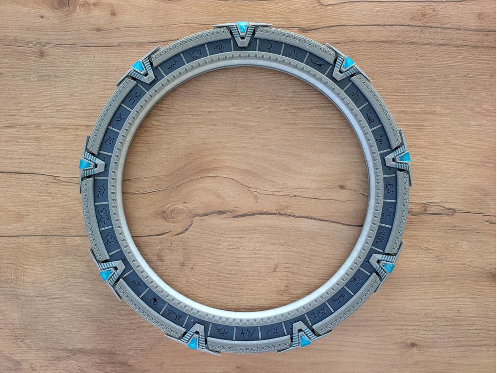
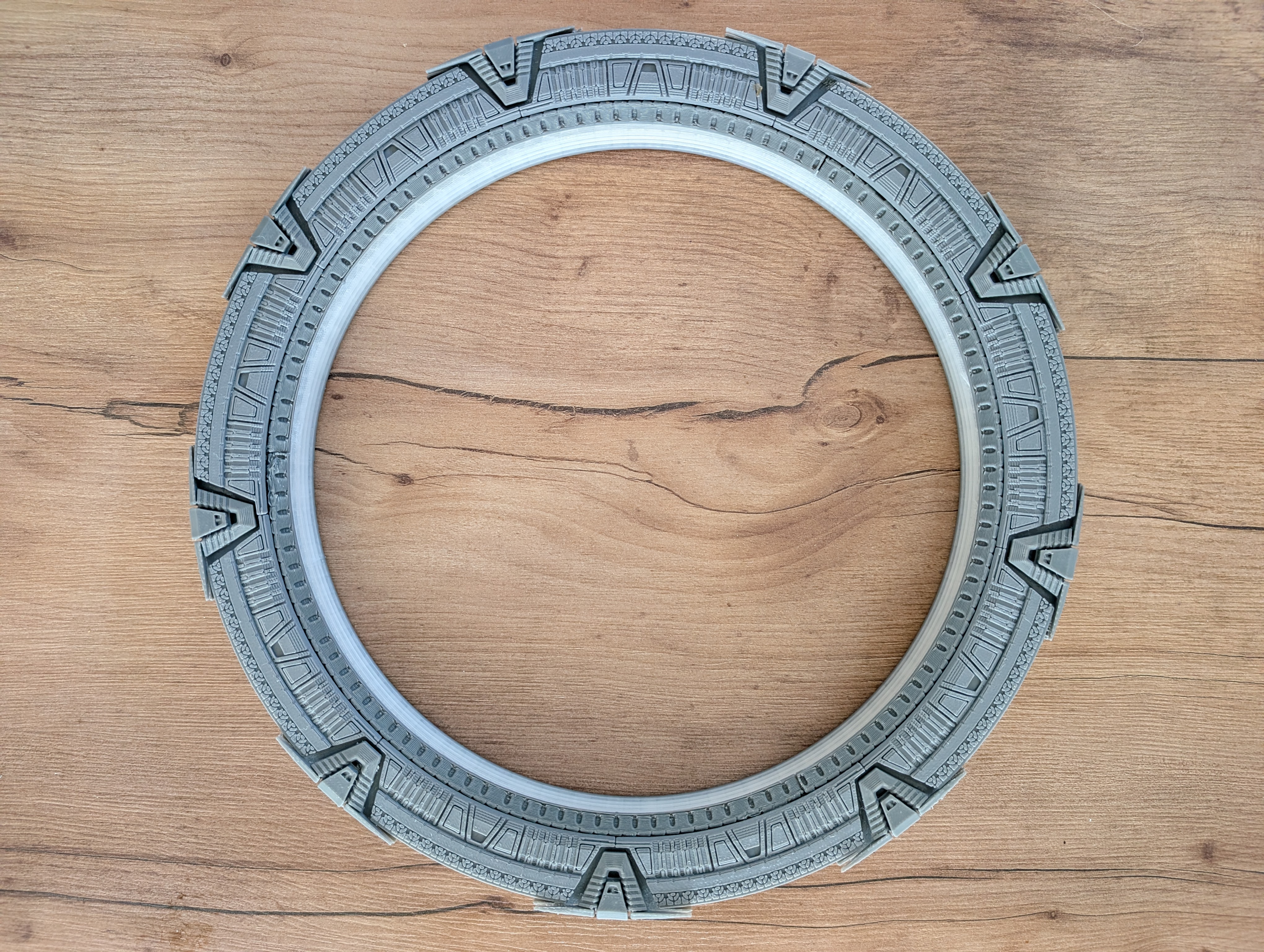
Model originally designed by Martin Taichl — just like every 15cm OpenGate gate. Visit Martin Taichl on MakerWorld.
Need help or have questions?
Join our community of builders on Discord to share your progress, ask for troubleshooting, or just chat about the project!
💬 Join the OpenGate Discord💡 About the LED Strip
This gate is designed around a single WS2812B strip, 96 LED/m, 10mm wide — keep about 210 LEDs on it (a little over 2m of strip). That single strip snakes through all three zones (chevrons, glyphs, event horizon) one after another.
It also works just as well built for three separate strips instead — you'll just need the PCB with three LED outputs to drive them. See the BOM / PCB Compatibility page for which board to use with which wiring.
3D Printed Parts
The model is split into five groups of parts:
- 1) Core ring — printable as a single piece, or cut into 3 sections if your printer's bed is too small. Supports are required to hold it to the print bed, but they aren't part of the model itself — it's actually recommended to disable any support that doesn't emerge directly from the bed. Otherwise you'll end up with support material stuck inside the ring, which is very hard to remove afterward.
- 2) Back & front gate covers (
gatecover_back×9,gatecover_front×9) — glue each onto its dedicated notch. The 9 back covers can be glued on right after the core ring is assembled. ⚠️ The 9 front covers must wait until the very end — after the LED strip, glyph ring, and everything else are installed. - 3) Chevrons (9 back, monochrome + 9 front). The front chevrons look best printed in two colors — transparent blue PLA for the center, grey PLA for the base and surrounding frame. No multicolor printer, or don't want the hassle? Print the whole piece in grey and just swap to transparent blue PLA for the center section.
- 4) Glyph ring — cut into 3 sections. The symbol inserts are optional: without them, the ring simply has open cutouts where each glyph symbol would be. Printed in translucent PLA instead, the ring looks solid/opaque when unlit, and each symbol lights up and becomes visible once the gate activates.
- 5) Interior ring / event horizon — grey base, with the edge/rim printed in translucent PLA.
Assemble the Core Ring
Start with the core ring. If you printed it split into 3 sections, join them with cyanoacrylate (super) glue and let it fully cure before moving on.
Then glue on the 9 gatecover_back pieces and the 9 back chevrons onto their notches. If the core ring was printed in 3 pieces, this also reinforces those seams: 3 of the 9 back covers happen to land right across a joint between two sections, gluing straight over it.
Remember: the 9 front covers stay off for now — they only go on at the very end, in a later step.
Route the LED Strip
Feed the strip in through the hole at the bottom of the ring — or more simply, loop it loosely into a circle and work it into the ring from the front, section by section. The LEDs must face inward, toward the center of the ring, all the way around.
The single strip makes three full loops, one per zone, in this order:
- All 9 chevrons first, going anti-clockwise.
- Then the glyph channel, for a second full loop.
- Then the event horizon channel, for the third and final loop — trim off whatever's left over.
Don't worry about perfect glyph alignment. Ideally you'll land on 2 LEDs per glyph, but if you only get 1, or if some LEDs straddle two glyphs instead of landing cleanly on one, that's completely fine — the advanced calibration mode in the DHD lets you assign each LED to a glyph by hand afterward, and it works very well.
Don't worry about a perfectly flat strip either. It's better if the strip presses flush against the outer wall along its whole length, but it'll still work well even if a few LEDs end up sitting a bit loose against the plastic. To help hold it flush: use the strip's own adhesive backing to stick it down section by section as you go, or run a bead from a low-temperature hot glue gun along the channel during assembly to pin it against the outer wall.
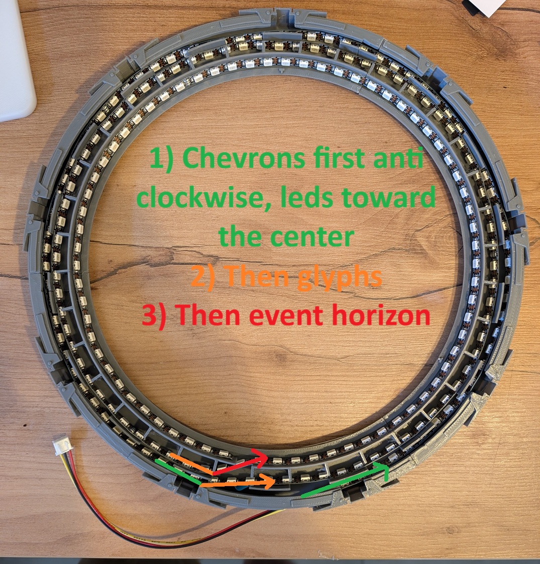
⚠️ Do NOT close up the gate before calibrating it. Calibration is much, much easier while everything is still open and visible.
Wire Up, Flash & Calibrate
With a single strip, everything is wired on one continuous data line. Which connector that plugs into depends on the PCB you're using — same board either way as the 15cm Pegasus, see the 15cm tutorial and the BOM / PCB Compatibility page for more on the boards themselves:
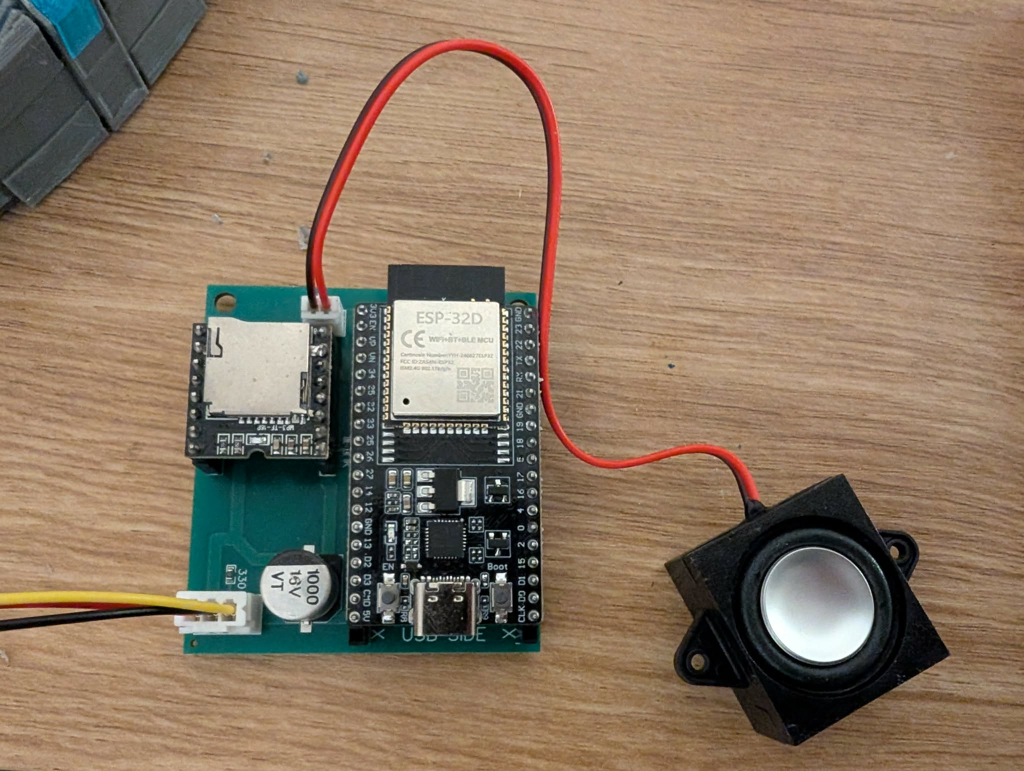
- Standard PCB V1 (three LED outputs) — plug the single strip into the chevron connector specifically. All three JST connectors are populated on this board whether you use one, two, or three physical strips.
- PCB V2 or V3 (built for a single strip) — there's only one LED output to begin with, so just plug straight in.
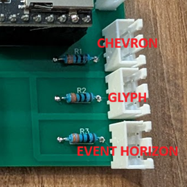
PCB V1 — which connector is which
PCB V2 — single LED output
Connect your ESP32 to your computer with a USB cable and open /flash/ in Chrome or Edge. Select Atlantis (same firmware profile as the 15cm Pegasus — gate size doesn't matter to the firmware) and Single LED strip, then connect and hold the BOOT button to start. Once flashed, the gate boots into its own Wi-Fi hotspot.
Connect to that Stargate-Setup-XXXX network (open, no password) — a setup page should open automatically, or open a browser and it'll redirect you there. Enter your home Wi-Fi details, plus your MQTT credentials if you've already joined the official network. Save & reboot: the gate connects to your Wi-Fi, and the confirmation page gives you its address — http://Stargate-<name>-XXXX.local/. Bookmark it, that's your gate's DHD from now on.
To join the official network (needed to dial other gates and receive incoming calls), a voluntary donation of at least €1 covers server costs — buymeacoffee.com/opengateproject — and you'll get your personal credentials to enter in that same setup form. Registering on the public directory to receive incoming wormholes is optional.
Open the DHD and use the LED calibration panel to check every LED lights up where you expect and, if needed, fine-tune the glyph assignment. You technically can calibrate after the gate is fully sealed up too — but it's far easier to catch and fix a wiring mistake before everything is glued shut, and doing it with the gate still open gives you a clear, direct view of every LED while you work.
Install the Glyph Ring
Place the glyph ring section(s) so that the Tau'ri (Earth) symbol lands at the 8th position, counting from the very top of the ring. This is what keeps the ring correctly aligned for Alternative dial mode — see the FAQ for the full explanation and diagram (it also covers Canonical mode, where the ring position doesn't actually matter, and how to fix it later with the calibration tool if it's off).
Front Covers & Interior Ring
Now that everything's wired, flashed, and calibrated, glue the 9 gatecover_front pieces onto their spots — this is the point they've been waiting for since step 2.
Finish by fitting the interior ring / event horizon. Tip: don't hesitate to scale it up by 3–4% in height in your slicer before printing — it makes it noticeably easier to fit into place.